[This discussion took place on our SARC-All email reflector – Ed.]
Bruce N9EHA started the discussion with this post.
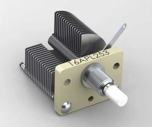
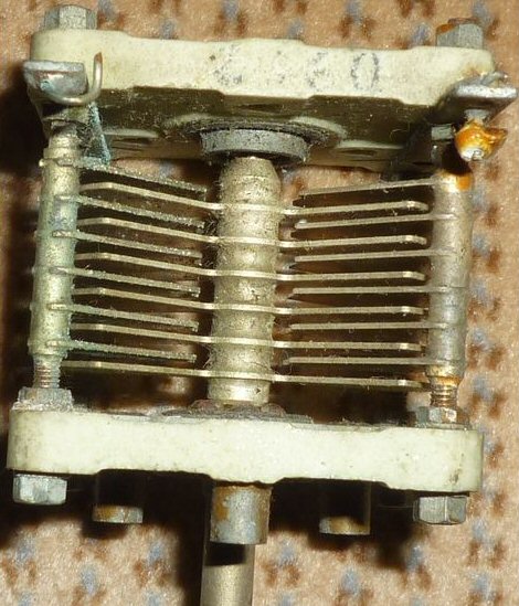
In older radios, in order to get the tuning dial scale to tune linearly across the band and not “bunch up” frequencies at one end of the scale, they used an air variable capacitor that would change capacitance non-linearly. If it had circular plates, the shaft was installed off center to make the capacitance change non-linear (first pic), or they had a tear drop shape, that looked like the second picture below, to get a logarithmic change in capacitance with rotation of the shaft.
The question is, what was the common name for these type of non-linear variable tuning caps in old radios? Someone at the construction project thought it also used to be a test question on one of the older license exams, but I couldn’t find it. If anyone remembers the name or nickname for them, let me know.
N9EHA followed up a few days later with this, closing the loop on the ongoing discussion.
Good discussion point to keep the thread going. Butterfly is a specific type of construction with a split stator. Butterfly capacitors are where the rotor plates are made in four 90 degree quadrants instead of the usual 2 halves (half circle), hence the so-called butterfly shape looking at the rotor plates from the end. A butterfly capacitor is the first one below, vs a normal variable capacitor below that for comparison.
The difference between standard and butterfly is in where the electrical connections are made. On a standard one (half circle), one electrical connection has to be made to the rotor plates via a moving connection. You can see the connection on the second picture sticking up towards the top right, and that connection needs to slide on the shaft when the cap is adjusted to maintain its connection. That’s fine in a receiver circuit, or other relatively low power design.
On a butterfly, each electrical connection is to each side’s (separate, split) stator, with no sliding connections made to the rotor. RF current goes into one side’s set of stator plates, and comes out the other set of stator plates, coupled through the rotor plates along the way. It’s easier to see in the 3rd pic where the solder connections are made to each side’s stator, with the butterfly rotor having no connections to it. That’s advantageous because you can get more current out of a solid weld, solder, or bolt to the frame where the stator plates are mounted, than you can out of a sliding connection to the rotor. So very high current capacitor needs, like in tank circuits for high power RF amps, have less loss and more power handling capability. You sometimes see them tuning small magnetic loop antennas for that same reason, due to the very high circulating currents when the loop is tuned.
Also note that a butterfly only has useful rotation of 90 degrees, not 180 like a standard. It will repeat the same capacitance value at FOUR points in a single rotation, not two points like a standard. Not a problem for the cap, just something you have to consider if you want to mechanically restrict the rotation on the shaft to not repeat, or to design the face panel markings on gear, etc.


