Websites Recommended by Club Members

Each month we present a new list of websites that club members find interesting. We’ll share these with you.   If you find something of interest that’s Ham Radio, or technology related, ie electronics, science, engineering, computers, kit building etc, please feel free to send submission to Mike K9KQX.

ARRL Repurposes AM Transmitter for HAM Radio Use – Thanks to a joint effort by ARRL and the Vintage Radio and Communications Museum of Connecticut (VRCMCT), a classic Gates BC-1T AM broadcast transmitter will enjoy a second life on the Amateur Radio bands for occasional use under W1AW or under the ARRL Headquarters Operators Club call sign, W1INF

Stephen Hawking, Who Awed Both Scientist and the Public, Dies – There aren’t very many scientists who achieved rock star status. Stephen Hawking, who has died at the age of 76, family members told British media early Wednesday, was definitely a contender.

BITX40 SSB Kit

by Dave Sims K9KBM

(Copied from Ad)

When was the last time you used a radio you had built? The BITX40 board is a two board, 40 meter SSB transceiver module kit with digital control! Inside an evening, you can be on-air with this digital SSB transceiver, chatting with the local gang or chasing DX across the world. Plug in the earphones, the included electret mic, tuning and volume controls, and you are on air! Included are high quality connectors, all the needed sockets and jacks, tuning and volume controls, mounting hardware, etc., all for $60.

Technicals

The BITX40 is shipped as a set of two boards : The Raduino and the Main Transceiver Board, with connectors and external components. You have to supply your own cabinet, mic, speaker, power supply and Antenna. Soldering is required, but all of the SMD and other components on the Main Transceiver Board and already soldered in place for you. Your kit-building efforts are little more than connecting the off-board controls via the supplied wiring connectors.

The Raduino

The new BITX40’s Raduino is a small, hackable, board utilizing an Arduino Nano to control a rock-steady Si5351 synthesizer and a clean 16×2 frequency display. The program code is free and Open Source. The Raduino features 6 analog ports, three oscillators and six digital lines.

Receiver

Listen to the very clean, crisp, and quiet receiver. The front-end has a triple-tuned circuit that limits out-of-band signals. The diode ring mixer front-end makes this a crisp receiver that doesn’t overload easily. The all-analog signal path to your ear provides outstanding signal clarity that must be heard to be believed.

Transmitter

7 watts of low distortion SSB provides you with enough power to have thousands of contacts on 40 meters, daily rag chews, and occasional DX chasing. Any common 2 ampere, 12 linear volts, power supply will provide enough juice for this transceiver. Or you could simply run it from a battery!

Hackable

The BITX40 will inspire you to experiment. Modify it, mount it, tweak it, change it. The Users’ Group is filled with plenty of ideas for modifications if you want to experiment.

Raduino uses a standard Arduino Nano that makes it easy to write code in simple C language to work on more modes, bands, utlilities. RIT, dual VFOs, more bands, CW/RTTY are just some code away! Who will be the first to add the Raduino keyer?

The main board comes with all analog large-sized SMD components already soldered on the board. The components are laid out on an easy-to-understand manner on a double sided board with broad tracks to encourage experimentation. There are jump-points from where you can add more modules like the DDS, more bands, better audio amplifier, etc. Your imagination is the limit. You can separately increase the power amplifier’s supply voltage to 25 volts to be more than 20 watts of power if you want. (You will have to add a larger heat sink.) The mods are on the way!

The boards can be installed inside any box that you like. Make your own station rigs, man-packs, SOTA rigs, trail radio, or mount it in a cigar box and leave it on your bedside table. Watch the instructions video.

Box Contents

We have tried to include all the connector/hardware you might possibly need to build a full radio. However, we also had to balance the shipping weight to keep the overall cost down. You will have to supply your own box, power supply and earphones/headphones/speaker.

  • 4-1/2 inches by 5 inches tested SSB transceiver module, covering any 400 KHz segment of the 7 MHz band
  • The Raduino board with Si5351, Arduino Nano with code loaded. Fully tested
  • High quality BNC connector for the antenna
  • Small electret microphone
  • Two earphone-style audio jacks for the mic and the earphones/speaker
  • A set of DC power socket and plug
  • Volume control with on/off switch
  • 10k linear pot for tuning
  • 8 brass standoffs with mounting nuts and bolts
  • Connectors with wires for all connections to the board

Note : A speaker is not included in the kit as earphones/headphones/speakers are easily available locally. No cabinet is included to save on the postage cost. Almost any box maybe used.

Manufacture

The BITX boards are hand assembled by a collective of women. Each of the toroids is hand wound. This provides these women with a livelihood. The assembled boards are then DC checked and a final RF check is performed to check the receiver’s sensitivity as well as transmitter’s output before being shipped. Each board is individually numbered.

Builders Comments

The most difficult part of this kit is deciding on a container and the mechanical work. You can find many on line pictures showing how to layout and (also how not to) your chassis /container. A few builders made 3D printed cases and offered a free download of their design, one that I particular like is shown below.


When using a plastic case you should line the case with foil tape, conductive paint or space the assembly off an un-etched PCB blank for best practice. I’ll give the instructions an A- and the pictorial an A. Depending on the layout some of the wire leads were long so I took the precaution of twisting the leads with a drill before I cut then to length. If you noticed in the case photo, one knob (the tuning knob) is bigger than the other which provides a better feel for tuning. As mentioned, the mechanical work takes the longest time and effort once completed the electrical portion only takes a few hours. One of the wiring options is to provide the power amp with a higher voltage supply allowing you to double the output.

Firing It Up

As a test, the instructions recommend monitoring the current while hooked to a dummy load and noting that the current jumps from .25A to 1 Amp when loudly speaking. That worked well on the dummy load but poorly (very little current change) on an unturned antenna. The receiver worked well on my long wire and station were not difficult to tune in as a large knob worked as a veneer.

Other Offerings

The same company offers a 40M rig and for $114 you can buy an 80 thru 10 transceiver.

Giving a Helping Hand to a HAM in need

By Dirk W0RI

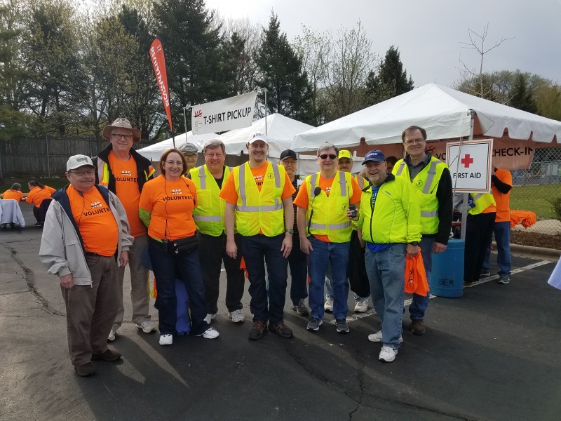
Ray Buchicchio WA9BLP Antenna Project, Roselle, Illinois, Saturday March 10, 2018

Site Profile (Ray Buchicchio):

Ray was born 1927 in Chicago, IL, his Elmer was his Ham Dad. Lives with wife Millie in Roselle, IL. Ray was a charter member of SARC going back his friend Bill Sneed. An interesting fact is that the SARC repeater was on his tower for many years !!! Small world !!!
Ray contacted me end of last summer on 2M, we chatted for a while and informed me that he needed help fixing his station. He has Rotor and antenna problems, in several discover visits it was confirmed something is wrong on the tower. A few days later we cranked the tower over to take a look. Very shortly upon inspection all coax cables were bad-damaged since they have been on the tower for close to 40 years. In the meantime Ron KD9IPO (donated for temp use) helped me install an end feed wire in -20 degrees weather, to get Ray back on the air until we could solve the coax problems etc. The early volunteers were Mike Sorenson, Peter Mazuik, Rob Glowacki, and Dirk Smith. Hence from that point the project was planned and scheduled during warmer weather, which turned out to be Saturday, March 10, 2018.
The project required new coax, which Ray purchased, 250 foot spool of 8U, I had a spare rotor cable and also purchased new PL259 and SO239 connectors.

Weather: Clear Skies, 34 – 45 degrees

Start Time 8:00 AM

End Time: 8:28 PM

Food Provided

AM Donuts- Coffee, lunch – pizza (donated by Dirk Smith W0RI)

Project Team

James Richardson AC9PH, Bill McGovern KD9JQM, Ron Delpiere-Smith KD9IPO, Rob Glowacki N9MVO,
Kevin Willard KB9QVX, Kevin Chin K9AAB, Peter Maziuk N9POL, Steve Karson AC9EM, John Schofield AC9JS,
Chris Brewer AC9GN, Mike Sorenson (plus daughter Katie)K9KQX, Dirk Smith W0RI,

You Tube Link: https://youtu.be/6WxyP60FYu8 by Kevin Chin K9AAB
Pictures: ALL Volunteers, Steve, James, Kevin W., Chris, Kevin C, Dirk, James at https://invertedlight.com/

Project Scope

  • Replace 4 Feedlines with new 8U COAX and a Rotor cable
    • 1x 3 Element Multi band Antenna
    • 1x Rotatable Dipole (Multi Band)
    • 1x 2 Meter antenna
    • 1x Fixed Dipole antenna
    • Rotor cable
  • Terminate cable with PL259 outside and solder to connection plate in shack, incl. Rotor cable
    • Replace SO239 connectors in shack
  • Replace Matching network on 3 element Multi Band Antenna
  • Visual Check of Rotor, replace junction box for rotor cable connection next to Rotor
  • Remove and reinstall fixed dipole from tower
  • Drape 5x cables on tower, feed cables into attic then down wall into shack, with drip loop, extra in 2 feet in attic
  • Verify operation when all ends terminated and tower raised again.
  • Check AMP and AMP power supply, both replaced with spare. (see detail write up from Rob, below)
  • Clean up yard and put away ladders and supplies

TBD: (remaining issues can all be done by simply by folding over tower)

  • Rotor repair or replacement does not fully rotate skips in some directions.
  • Determine is 20 M band was dead, or Antenna issue or FTDX1200 radio/configuration
    • 20 M coils bad?
    • FTDX1200 took a hit on 20M?
  • Drop 2M antenna approximately 2-3 feet, interferes with antenna rotate loop.

SHACK WORK

Report from Rob Glowacki N9MVO (Kevin Willard KB9QVX)

Also, he had some rather unusual connections in his shack. The FT 1200 was connected to the ‘antenna’ connector of the SWR/Power meter, the SWR power meter’s ‘transmitter’ connector was hooked to the ‘antenna’ connector of the MFJ auto tuner, and the ‘transmitter’ connector of the MFJ was connected to the input of the amp. At least the amp was connected correctly.
The SWR/Power meter was backwards, which made ‘forward’ and ‘reflected’ power readings reversed, but worse than that, the MFJ tuner was connected backwards. That *might* have caused it to try to tune for lowest ‘forward’ reading, and most ‘reflected’ reading, as forward and reflected would be reversed with that connection.
When we first got things connected, we heard NO signal on 20 meters at all, we found that the attenuator on the radio was turned on, at -18 dB. That would kinda reduce signals by about 3 S units. You know of the Antenna 1/ Antenna 2 switch
problem. He said the 1200 rig is rather new, so he’s not real familiar with it, yet. He may need a little hand holding to help him get things set up right for usual operation.
Of course, he also needs to have the 80 Liter antenna coax connector mounted on the wall, on a plate of some sort, and yet another coax jumper cable made to connect THAT to the antenna switch.
His backup amplifier power supply, the switching supply, smells of burning resistor shortly after getting turned on. Both amplifiers work, at about the same power output level, with the same 45 Watt input. The amp he usually uses indicates on its own meter about 550 Watts, the backup amp on the shelf indicates about 300 W output with 45 W drive.
Both amps show about 300 W on the same external power meter (his meter) and about 500 Watts on my genuine Radio Shack power meter, that MUST be made for CB, because it has a 2000 Watt scale (;^D) Actually, the package for it says it has a Buene bridge, which should be accurate across the HF bands. I know the 20 and 200 Watt scales on it are pretty close. I don’t use the 2 KW scale, so I don’t know how close that reading is.
The backup amp DID work on the backup power supply before we started smelling smoke, so it apparently was putting out SOMETHING for a while. We shut it down as soon as we smelled something bad..
It was a very worthwhile effort! Now we need to figure out what’s wrong with the tribander on 20 Liters, and the rotatable dipole on 10 and 40 Liters.

The WORK

(+12 hours)
In Garage: Mike K9KQX prepped the coax 8U cables and soldered new PL 259 on ends. (Daughter Katie keeping an eye on Dad)
Roof Crew: Kevin C, Bill Cable drape, fixed Dipole remove and install (final tower tilt back work Dirk)
Spotters: John, Steve
Antenna: Ron, Chris, James, Dirk
Rotor: Ron, Peter, James, Dirk
Shack: Kevin W., Rob, Ron (solder cables, solder rotor cable, test power supplies and Amplifier)
Attic: Dirk, Kevin C., James, Kevin W.

Although the project is not 100% completed, Ray is back on the air with his Amplifier. Ray and Millie were very impressed with the courtesy and work ethics on this project. He could not get over the fact that so many people showed up to help him repair his issues. What I mentioned to Ray: “ You risked your life/ limbs in WW II, for many, it is now our turn to do this small thing for you ,as a token of our appreciation, as a Veteran,  fellow Amateur Radio Operator and charter member of SARC.”   In the next week or so I and Mike K9KQX RHG Editor, will feature Ray’s life profile in the RHG.

A personal message from me: Although I was not born in the USA, but did become a citizen, I was proud to have this kind of response and Crew working to help Ray. Looking back I believe we had the right number of volunteers, I actually had to turn people away prior to project start.

Thank You again on behalf of a very grateful Ray and wife Millie…..

Update (06/05/2018): Ray WA9BLP Antenna Project Update


CQ Worked All Prefix Contest

From 7pm Friday, March 23 until 7pm Sunday March 25 you can work countries around the world on HF SSB. The goal of this contest is to work as many prefixes as possible, with more points earned for countries on a different continent than you. The exchange for this contest is very simple, 59 and a serial number. Start with one and give each successive contact the next serial number in line.

CQ SPX SSB contest details

VE Testing

John Shofield provided the following report:  Results March 3rd, 2018

Name Call Class
Walgenbach, Neil E. AC9SK Extra
Chen, Hao KD9KLX Technician
Richier, Taylor L. KD9KLY Technician
Bizon, Bartlomiej KD9KLZ Technician


Class  
Technician 3
General 0
Extra 1
Total 4

Next examination date: April 7th, 2018

All of us at SARC would like to congratulate all those that received or upgraded their license this month, and we welcome you to the amateur radio community.  Hope to hear you on the air.   Should you have any questions, come join SARC at our regular monthly meeting on the 3rd Thursday of the month or stop in at one of the Construction Meetings.