SDR Radio with the Ettus USRP B206 mini-i
Compact Power for Wireless Innovation
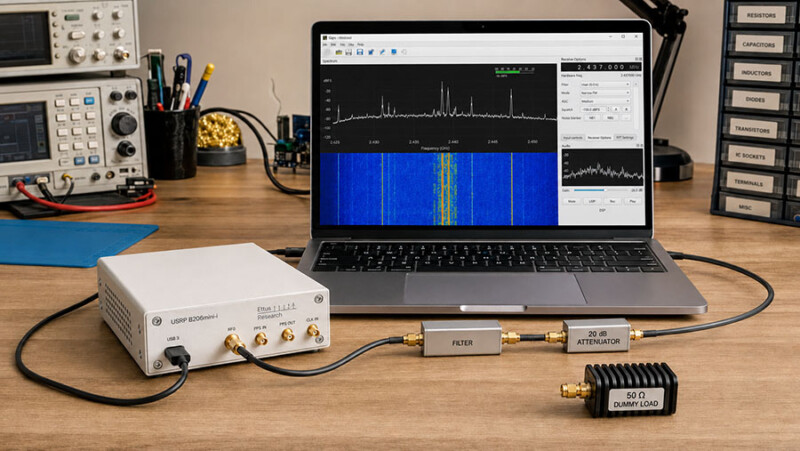
Here is a useful experimentation idea for SARC members: build a flexible software-defined radio bench around the Ettus USRP B206mini-i. Instead of buying a radio designed around one mode, this compact platform lets software define much of the receiver, transmitter, measurement, and signal-processing path.
DigiKey highlights the B206mini-i for wireless communication research, spectrum monitoring, education, and embedded development.[1] For SARC, the interesting question is not simply what the device can receive or transmit. It is what we could learn by building a repeatable experiment around it.
Post idea from Paul Meyers – KE9EJX.
Topic Snapshot
| Item | Details |
|---|---|
| Subject | Building a Flexible SDR Radio with the Ettus USRP B206mini-i: Compact Power for Wireless Innovation |
| Platform | Ettus USRP B206mini-i software-defined radio |
| Radio architecture | One transmit path and one receive path with full-duplex capability |
| Tuning range | 70 MHz to 6 GHz |
| Instantaneous bandwidth | Up to 56 MHz |
| Software | USRP Hardware Driver (UHD) 4.9 or later, GNU Radio, C/C++, or Python |
| Best first project | A receive-only spectrum display or narrowband receiver |
| Audience | SARC members, visitors, new hams, the public, operators, and volunteers |
| Call to action | What could you do with a device like this? |
| Product overview | View the DigiKey product highlight |
What Makes an SDR Different?
SDR means software-defined radio. The radio still needs real analog hardware for antennas, filtering, gain, frequency conversion, and data conversion. However, many functions that would be fixed in a conventional radio can be changed in software.
A member can change the center frequency, sample rate, receiver gain, filter width, demodulator, decoder, display, recorder, or transmitted waveform without rebuilding the complete radio. That makes an SDR useful for learning because each block in the signal chain can be viewed, adjusted, and measured.
The B206mini-i is a 1×1 platform. In plain language, it has one transmit path and one receive path. Full duplex means those paths can operate at the same time when the software and external RF system are designed correctly. It does not mean that the unit has two independent receive channels.
What the B206mini-i Brings to the Bench
| Feature | Specification | Why It Matters |
|---|---|---|
| RF coverage | 70 MHz to 6 GHz | Covers many VHF, UHF, and microwave experiments. It does not directly cover the HF or 6-meter amateur bands. |
| Instantaneous bandwidth | Up to 56 MHz | Lets software examine or generate a wide slice of spectrum at one time. It does not view the complete 70 MHz-to-6 GHz range at once. |
| RF channels | 1 TX and 1 RX, independently tunable | Supports receive, transmit, and carefully designed full-duplex experiments. |
| Measured maximum TX output | 16.06 dBm from 70 MHz to 4 GHz; 9.16 dBm from 4 GHz to 5.9 GHz | Provides a low-level RF source for controlled experiments. Output varies with frequency, and these values are not permission to transmit. |
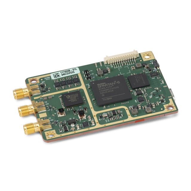
| RF and digital hardware | Analog Devices AD9364 transceiver and Spartan-6 XC6SLX150 FPGA | Combines a flexible RF front end with programmable digital logic. |
| Data conversion | 12-bit ADC and 12-bit DAC; maximum I/Q sample rate of 61.44 MSa/s | Provides complex digital samples for software processing. Actual usable rates depend on the complete host and application. |
| Host connection | Bus-powered USB 3 Type-C; 5 V DC at 0.9 A maximum | Moves samples and power through one compact host connection. |
| Timing reference | External 10 MHz clock or pulse-per-second (PPS) reference | Supports experiments that need improved frequency or time coordination. |
| Expansion | Eight 3.3 V GPIO lines and JTAG | Allows hardware control, triggering, FPGA programming, and debugging for advanced work. |
| Physical versions | Board-only or enclosed; enclosed unit is 84.9 mm × 55.7 mm × 19.8 mm and 108 g | The manufacturer specifies indoor, noncondensing use. Before operation, the board-only variant must be installed in a suitable shielded enclosure that also meets the stated fire and mechanical end-product enclosure requirements. |
The 56 MHz figure is a maximum instantaneous bandwidth, not a requirement. A first project should use only the sample rate and bandwidth it needs. Smaller settings reduce host processing, storage, and USB demands.
How the Signal Path Works
On receive, the AD9364 RF front end tunes and converts a selected part of the spectrum into in-phase and quadrature samples, usually called I/Q data. Those two sample streams preserve amplitude and phase information. The FPGA manages timing and high-rate digital work. USB carries the samples to the host computer, where UHD connects the hardware to GNU Radio or a custom program.[3]
---
config:
  markdownAutoWrap: true
  flowchart:
    wrappingWidth: 220
    useMaxWidth: true
    nodeSpacing: 40
    rankSpacing: 50
---
flowchart TD
    A["`Antenna or protected
test source`"]

    B["`AD9364 RF
front end`"]

    C["`Spartan-6 FPGA
and I/Q samples`"]

    D["`USB 3 Type-C
connection`"]

    E["`UHD hardware
driver`"]

    F["`GNU Radio, Python,
or C/C++`"]

    G["`Display, decode,
record, or measure`"]

    A --> B
    B --> C
    C --> D
    D --> E
    E --> F
    F --> G
Most new users can begin in GNU Radio Companion, where blocks are connected into a visual flowgraph. FPGA modification is possible, but it is an advanced step. A good first build leaves the supplied FPGA image alone and concentrates on a stable receive path.
Experiment Ideas for SARC
| Experiment | Starting Mode | What It Teaches |
|---|---|---|
| Waterfall tour | Receive only | Center frequency, sample rate, gain, noise floor, occupied bandwidth, and visible interference |
| VHF or UHF FM receiver | Receive only | Channel filtering, FM demodulation, squelch, audio recovery, and signal-to-noise ratio |
| Antenna or filter comparison | Receive only | How signal level, noise, overload, and selectivity change when one RF component is changed |
| Digital signal recorder and decoder | Receive only | I/Q recording, sampling, digital demodulation, clock recovery, and repeatable offline analysis |
| Frequency-reference comparison | Receive only | Use an external 10 MHz reference to study oscillator drift and frequency accuracy, or PPS to study timestamp and time alignment. |
| Attenuated loopback | Shielded bench test | Waveform generation, occupied bandwidth, filtering, attenuation, and receiver dynamic range |
| Low-power amateur digital experiment | Licensed and measured transmit setup | Modulation, identification, minimum necessary bandwidth, spurious-output control, and link testing |
What You Need
- An enclosed Ettus USRP B206mini-i, or a board-only variant installed in a suitable shielded enclosure that also meets the manufacturer’s fire and mechanical end-product enclosure requirements
- The correct USB 3 Type-C data cable and a host computer with a suitable USB connection
- A current supported UHD release; the manufacturer specifies UHD 4.9 or later
- GNU Radio for visual flowgraphs, or C/C++ or Python for custom applications
- A band-appropriate antenna, 50-ohm coax, and the correct SMA adapters for receive-only work
- Filters, attenuators, or a preamplifier selected for the specific experiment
- For transmit testing: a suitable 50-ohm dummy load, verified attenuation, output filtering, and a way to examine the transmitted spectrum
- A notebook or shared project log for frequency, sample rate, bandwidth, gain, antenna, filter, software version, and results
Check the current NI, Ettus, and DigiKey pages before ordering. Availability, package contents, software support, and pricing may change.
A Practical First Setup
- Choose one receive question. For example, decide to display a known local signal, compare two antennas, or measure how a filter changes the noise floor.
- Connect the receive path. Use the RX2 connector, a suitable antenna or protected test source, and any needed receive filter or attenuation. Do not connect another transmitter directly to the input.
- Install UHD and verify the hardware. Ettus documents
uhd_find_devicesfor discovery anduhd_usrp_probefor reporting device properties.[4]
 uhd_find_devices
uhd_usrp_probe- Build the smallest useful flowgraph. In GNU Radio Companion, begin with a UHD: USRP Source and a frequency or waterfall display. A hardware USRP Source supplies the timing, so a Throttle block is not needed in that path.[5]
- Start modestly. Select a narrow sample rate, begin with low receive gain, tune a known signal, and increase gain only as needed. Watch for overload and dropped-sample warnings.
- Change one setting at a time. Record the center frequency, sample rate, analog bandwidth, gain, antenna, and observed result before making the next change.
- Save the working baseline. Keep the flowgraph and notes together so another SARC member can reproduce the demonstration.
Protect the Radio and the Test Bench
The B206mini-i is sensitive laboratory hardware. Ettus says to terminate the transmit port in a suitable antenna or 50-ohm load, never apply more than −15 dBm to an RF input, and use at least 30 dB of attenuation for loopback operation.[6] Never connect the transmit port directly to RX2.
Use shielded I/O cables no longer than 3 m (10 ft), protect the hardware from electrostatic discharge, and keep it away from water and condensation. Power it only from a suitably rated and certified USB source with a Class 2, Limited Energy, or LPC output. Before operation, the board-only variant must be installed in a suitable shielded enclosure that also meets the stated fire and mechanical end-product enclosure requirements.[7]
NI describes the product as intended for indoor use. The enclosed version has a wider specified operating-temperature range, but that does not make it weatherproof.[7]
Before Any On-Air Transmission
A tuning range is a hardware capability, not permission to transmit. NI also states that the product itself is not approved or licensed for over-the-air antenna transmission and tells users to determine compliance with local law.[7] Treat the B206mini-i as experimental RF hardware, not as a finished plug-and-play amateur transceiver.
For a United States amateur-radio experiment, begin with receive-only work. Then move to a dummy load or shielded path, measure the output, add the correct filtering, verify power and RF exposure, and only then consider an antenna. Current Part 97 rules permit brief test emissions for experimental purposes only on frequencies authorized to the control operator and subject to the applicable emission limits.[8]
Before transmitting, the licensed control operator must confirm the authorized band segment and emission, keep the occupied bandwidth no wider than necessary, control spurious output and interference, use the minimum power needed, identify the station correctly, and determine whether the station qualifies for an RF-exposure exemption or requires an evaluation.[9][10][11][12]
Suggested SARC Goals
| Participant | Suggested Goal |
|---|---|
| Visitor or member of the public | Follow one signal from the antenna to the waterfall and identify the purpose of center frequency, sample rate, and gain. |
| New ham | Build a receive-only display, tune two signals in covered amateur bands, and record the settings that worked. |
| Active operator | Create a reusable VHF or UHF receive chain and compare two antennas or filters while holding other settings constant. |
| Programmer | Use UHD with Python or another supported language to capture timestamped signal-level or spectrum measurements. |
| Builder | Assemble a protected RF input path with a filter, attenuator, labeled cables, and a written maximum-level check. |
| Advanced experimenter | Generate a waveform into an attenuated bench setup and verify its occupied bandwidth and unwanted emissions before considering antenna use. |
| SARC project team | Build a receive-only demonstration kit with a tested flowgraph, a short operating card, and transmit disabled by default. |
Give It a Try
The B206mini-i brings RF hardware, digital signal processing, software, measurement, and programming together on one small bench. A newcomer can begin with a waterfall. An experienced builder can work on filtering, timing, automation, or a controlled waveform. Both are doing useful amateur-radio experimentation.
Start with one question. Build the smallest receive-only flowgraph that can answer it. Keep good notes. Then share the setup and the result with another SARC member.
What could you do with a device like this?
Choose one receive-only experiment, document it, and share what you learn with SARC.
Explore how the compact Ettus USRP B206mini-i can support receive-only SDR projects, GNU Radio experiments, controlled RF testing, and wireless communication research for SARC members.
References
- “Ettus USRP B206mini-i Compact Power for Wireless Innovation.” DigiKey. September 29, 2025. Accessed July 30, 2026. Full URL: https://www.digikey.com/en/product-highlight/n/national-instruments/ettus-usrp-b206mini-i-compact-power. ↩
- “USRP B206mini-i Specifications.” National Instruments and Ettus Research. Revision 379222A-01, September 2025. Accessed July 30, 2026. Full URL: https://www.ettus.com/wp-content/uploads/2025/09/usrp_b206mini-i_specifications.pdf. ↩
- “USRP B206mini-i.” Ettus Research, a National Instruments Brand. Accessed July 30, 2026. Full URL: https://www.ettus.com/all-products/usrp-b206mini-i/. ↩
- “Device Identification.” USRP Hardware Driver and USRP Manual. Ettus Research. Accessed July 30, 2026. Full URL: https://files.ettus.com/manual/page_identification.html. ↩
- “USRP Source.” GNU Radio Wiki, GNU Radio Project. Last modified September 26, 2023. Accessed July 30, 2026. Full URL: https://wiki.gnuradio.org/index.php/USRP_Source. ↩
- “USRP B2x0 Series.” USRP Hardware Driver and USRP Manual. Ettus Research. UHD manual version 4.10.0.0 displayed at access. Accessed July 30, 2026. Full URL: https://files.ettus.com/manual/page_usrp_b200.html. ↩
- “USRP B206mini-i Safety, Environmental, and Regulatory Information.” National Instruments. Document 327928A-01, September 1, 2025. Accessed July 30, 2026. Full URL: https://docs-be.ni.com/bundle/usrp-b206mini-i-seri/raw/resource/enus/usrp-b206mini-i-seri.pdf. Return to citations: a, b, c.
- “47 CFR § 97.305: Authorized Emission Types.” Electronic Code of Federal Regulations. Accessed July 30, 2026. Full URL: https://www.ecfr.gov/current/title-47/chapter-I/subchapter-D/part-97/subpart-D/section-97.305. ↩
- “47 CFR § 97.307: Emission Standards” and “47 CFR § 97.313: Transmitter Power Standards.” Electronic Code of Federal Regulations. Accessed July 30, 2026. Full URLs: https://www.ecfr.gov/current/title-47/chapter-I/subchapter-D/part-97/subpart-D/section-97.307 and https://www.ecfr.gov/current/title-47/chapter-I/subchapter-D/part-97/subpart-D/section-97.313. ↩
- “47 CFR § 97.119: Station Identification.” Electronic Code of Federal Regulations. Accessed July 30, 2026. Full URL: https://www.ecfr.gov/current/title-47/chapter-I/subchapter-D/part-97/subpart-B/section-97.119. ↩
- “47 CFR § 97.13: Restrictions on Station Location.” Electronic Code of Federal Regulations. Accessed July 30, 2026. Full URL: https://www.ecfr.gov/current/title-47/chapter-I/subchapter-D/part-97/subpart-A/section-97.13. ↩
- “47 CFR §§ 1.1307 and 1.1310: Radiofrequency Exposure Evaluation and Limits.” Electronic Code of Federal Regulations. Accessed July 30, 2026. Full URLs: https://www.ecfr.gov/current/title-47/chapter-I/subchapter-A/part-1/subpart-I/section-1.1307 and https://www.ecfr.gov/current/title-47/chapter-I/subchapter-A/part-1/subpart-I/section-1.1310. ↩